Draw block diagram of digital frequency meter in time mode and describe its operation. In order to measure large voltages, potential divider networks can be made on the input of.
Digital Multimeter Block Diagram And Working. The slope of the output voltage (eo) is determined by the value of input voltage (ei). Explanation of digital multimeter by using block diagram.
 What is Ship�s Block Diagram Electrotechnical Officer (ETO) From electrotechnical-officer.com
Apart from these, a digital multimeter can also measure temperature, frequency, capacitance, continuity, transistor gains etc. The input which should be measured is given at input voltage. For showing various measurements, a lcd display is used.
What is Ship�s Block Diagram Electrotechnical Officer (ETO)
The basic circuit of a digital multimeter is always a d.c. The digital multimeter is an instrument which is capable of measuring a.c. Block diagram of digital multimeter. An input attenuator, an electronic amplifier, and an electromechanical voltmeter stage.
 Source: circuitstoday.com
As we can see, the block diagram consists of attenuator with an analogue to digital converter after it. For showing various measurements, a lcd display is used. Voltmeter as shown in the fig. How ac ,dc voltages, current and resistance are measure by using digital multimeter? The basic block diagram of a typical integrating type digital voltmeter ( dvm) is.
 Source: finalsemeceprojects.blogspot.com
As we can see, the block diagram consists of attenuator with an analogue to digital converter after it. It consists of a 1 khz oscillator and a current to voltage converter, it is nothing but an operational amplifier. The signal may be amplified before being applied to schmitt trigger. Below the digital readout is a black dial, called the function.
 Source: wiring121.blogspot.com
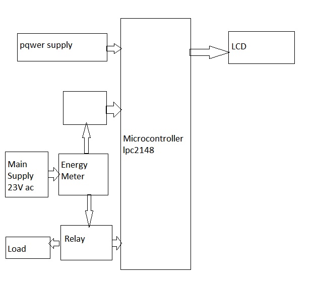
The input which should be measured is given at input voltage. This adc unit basically distinguishes between various types of digital voltmeters which we will discuss later. 1 shows the simple block diagram of a digital trivector meter. Block diagram of digital multimeter. The basic circuit of a digital multimeter is always a d.c.
 Source: electrotechnical-officer.com
(also called digital ramp) •the most simple a/d •slow conversion and conversion time depends on the magnitude of input signal. The block diagram of a digital l.c.r. Proposed model of digital multimeter is preferable dueto their accuracy, durability and extra features. The trivector meter gets input supply to be measured through current and potential transformers (ct and pt). This adc.
 Source: edgefx.in
The block diagram shown above is ramp type digital voltmeter(dvm). (also called digital ramp) •the most simple a/d •slow conversion and conversion time depends on the magnitude of input signal. Here is the working principle of integrating type digital voltmeter (dvm). Meter is shown in figure. The digital multimeter is an instrument which is capable of measuring a.c.
 Source: analyseameter.com
The input signal is amplified and converted to a square wave by a schmitt trigger circuit. The measurement of dc quantities will be done by exciting the bridge with dc voltage. Meter is shown in figure. The digital multimeter is an instrument which is capable of measuring a.c. D/a output time v ax clock period v in t (2n 1).


